In this post I will discuss setting up an IPFire based firewall appliance via a console serial cable.
Overview
This firewall appliance was built as a hobby project to use at home with my internet connection. The current generation of wireless routers tend to present your internet connection as a black-box without really providing any real information about their functioning. This project is an attempt to expose a little more about what is going on, as well as an opportunity to explore additional software such as DNS, DHCP, and Proxy/Caching services.
Hardware
My goal for the hardware was a fanless machine, with a small footprint, and reasonably priced. After looking around at various sites, I decided to purchase the parts from Mini-Box for around $260.
Parts list:
- mSATA-32GB ($65.00)
- Enclosure 3 LAN, USB for Alix.2, Black Version ($14.95)
- 24w (12V/2A) AC-DC Power Adapter with Power Cord ($9.95)
- APU1C4 T40E APU, 3 LAN, 2 miniPCIe, 1 mSATA, RTC battery, 4GB ($169.00)
From the catalog page at the Mini-Box site, the motherboard has the following specifications:
- AMD G Series T40E APU
- 1GHz Dual Core
- Built in 4GB DDR3 1066 DRAM
- 1 USB port, 1 COM
- RTC battery
- Built-in DC-DC converter
- Consumes only ~6watts
- Heat spreader included
- RoHS compliant
- Size: 152.4 x 152.4mm (6x6 in)
References and Manuals:
Software
I looked at several different firewall distributions before deciding on IPFire. Some of the other distributions I considered were:
In the end, IPFire was chosen because it is strictly a community based distribution, is actively developed, and focuses on the core functionality of a firewall.
To quote the IPFire website:
IPFire is a hardened Linux appliance distribution designed for use as a firewall.
It offers corporate-level network protection for anyone who needs it, from home users all the way up to large corporations, school networks and authorities.
IPFire focusses on security, stability and ease of use. A variety of add-ons can be installed with a single click, to add more features to the base system.
Making the Installation Media
To prepare the installation media you will need a spare USB drive of minimal size, I used 500 MB, and a copy of the latest ISO from IPFire’s Site.
First, I use the diskutil command via Terminal to help identify the USB disk that I will be using.
diskutil list

In the image above, I see two volumes: /dev/disk0 and /dev/disk1. I see that disk0 has a partition of type Apple_HFS with a name of “Macintosh HD”. This is the name of my iMac’s boot volume therefore I want to target the other disk (i.e. /dev/disk1) for writing the IPFire boot image to.
Still in the terminal, I need to execute the command below to unmount the disk that I will be writing to.
diskutil unmountDisk disk1
After a few moments I would expect the message “Unmount of all volumes on disk1 was successful”.
Finally, I can write the boot image to the target disk with the command below. I need to elevate my privileges using sudo since I am writing to a device file.
sudo dd if=ipfire-2.15.i586-full-core81.iso of=/dev/rdisk1
Connecting the Serial Console
At this point I have the bootable USB stick inserted into the appliance and have connected the serial console cable to a spare USB port on my iMac. Next I need to connect a terminal session to that cable, before I power on the device.
I am using the Prolific PL2303 USB to Serial Port Cable. The driver can be downloaded from the Support section of their website.
NOTE: To download this particular driver you do not have to login to the support site as the popup dialog would seem to suggest. There is a link on the page to for the PL2303 Windows/Mac/Android Driver page.
The Prolific driver software creates a device named /dev/cu.usbserial and according to the motherboard manual I need to connect at 115200 baud. I can do this using the screen program executed from the Terminal program, as shown below. Again I need to elevate my privileges because I am working directly with a device file.
sudo screen /dev/cu.usbserial 115200
I had some initial issues with the installation program improperly displaying via the screen program and ended up using the following Terminal preferences:

The Prolific USB to Serial Port adapter has a male serial port connector as does the APU.1C4 console out port. This means that you will need a 9-pin serial gender changer between the appliance and the Prolific adapter. In my case I plugged a Cisco Serial (female) to RJ45 cable (male) adapter into a RJ45 (female) to Serial (female) adapter. Then plugged the Serial (female) adapter into the Prolific male (serial) end.
Booting Device and Installation
At this point the appliance can be powered on to begin installation.
I needed to specifically request the installation via the serial console by typing ipfire-serial at the boot prompt.

Select the language to be used by the installation program.

View the installation Welcome screen.

Accept the license agreement.

Confirm that the installation program can overwrite the contents of your installation disk.

Select the filesystem for your disk. (NOTE: I was unsure if the mSATA drive was actually considered a flash drive or not, so I chose Ext2 to be safe.)

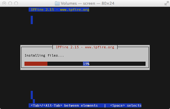
Viewing the installation progress.
Installation has completed, confirm the reboot.

Out-of-Box Configuration
After the initial reboot, first time configuration can occur. Here I am viewing the grub boot loader screen. It will automatically timeout and boot the primary entry.

Select the type of your keyboard.

Select your timezone.

Assign a hostname for the firewall.

Assign the domain for the firewall. In this case my firewall is internal to my home network so I am just going to use localdomain.

Enter the password for the root user. This will be the user that you use either from the console connection or via an SSH session.

Enter the password for the admin user. This will be the user that you use to access the web administration pages.

Select network configuration. The default is GREEN + RED. The GREEN network represents the machines on the internal side of the firewall (i.e. your home or business network) and the RED network represents the machines on the external side of the firewall (i.e. the internet). You can also choose ORANGE for DMZ machines which are internet exposed machines that reside between the GREEN and RED zones. There is also a BLUE zone which can be used to segregate wireless networks from the internal network. My setup just requires an internal and external zone.

Change or confirm the network configuration type.

Start to assign network interface ports to the different zones. Since I am using two zones, I will need two of the three network ports on the appliance.
Assigning the GREEN network port.

The purpose of the Identify command would seem to indicate it would flash the link lights in some manner to indentify the port but I was unable to get this function to work.

Assigning the RED network port.


Reviewing and confirming the selections using the Done button.

Assign address settings to each of the zones.

First the GREEN zone (i.e. your internal network).

We can ignore this warning because we are connected via the serial console, but you should remember in the future if you connect through a SSN session you could potentially disconnect yourself.

Assign the IP address and network mask for the GREEN interace.

Now we configure the RED zone (i.e. the cable modem network)

In my case the internet connection address is assigned by the cable provider via DHCP. The only option I can optionally configure here is the DHCP Hostname. I opted to change it to firewall rather than use the hostname again.

Assign DNS and Gateway settings to the RED zone. In this case those settings are supplied via the DHCP so I can leave them blank. I could optionally use a different DNS provider if I wanted to.


Assign DHCP server information to be used for the GREEN zone.

Configuration is done, click Ok to reboot.

Viewing reboot progress through the console.


Deploying the Firewall
After the appliance has rebooted the first time after installation is completed, I will need to shut it down cleanly in order to deploy it.
At the console screen, I need to login as the root user using the password I specified during installation, and execute the following command:
shutdown -h now
Once the device has powered off I can disconnect the serial cable and connect to the cable modem and wireless router. The cables are connected in the following manner:
- The WAN connection from the wireless router goes into the GREEN network port on the appliance
- The WAN connection from the cable/dsl modem goes into the RED network port on the appliance
NOTE: Because I opted for the firewall appliance to handle firewall and DHCP activities, I also needed to connect to the wireless router and turn off NAT and DHCP functions. This effectively makes the wireless router a bridge to the firewall appliance.
Once the firewall appliance is up and running you can connect to the web interface on port 444 with the IP address you assigned to the GREEN interface.
http://192.168.1.1:444
I can still use the serial console cable, the screen program, and a laptop to connect to the console port in the future should the web interface not be accessible.
Closing Remarks
In this post I demonstrated a cheap and fun way to experiment with hardware and software while building a practical firewall appliance for your home or small business network.